Page 10 - MILLING_CATALOG_INCH_2022_P593-P866
P. 10

INTRODUCTION
      TOOLING SYSTEMS

         ADJ Operating Instructions


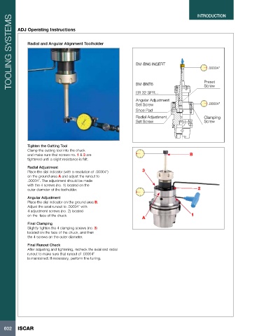
              Radial and Angular Alignment Toolholder


                                                                 BM-BN6 INSERT
                                                                                                   .00004"


                                                                                                 Preset
                                                                 BM-BNT6                         Screw

                                                                 ER 32 SPR...
                                                                 Angular Adjustment
                                                                 Set Screw                         .00004"
                                                                 Shoe Pad
                                                                 Radial Adjustment               Clamping
                                                                 Set Screw                       Screw


              Tighten the Cutting Tool
              Clamp the cutting tool into the chuck
              and make sure that screws no. 1 & 3 are                                      B
              tightened until a slight resistance is felt.

              Radial Adjustment
              Place the dial indicator (with a resolution of .00004”)    3
              on the ground area A and adjust the runout to
              .00004”. The adjustment should be made
              with the 4 screws (no. 1) located on the
              outer diameter of the toolholder.                                                2

              Angular Adjustment
              Place the dial indicator on the ground area B.
              Adjust the axial runout to .00004” with
              4 adjustment screws (no. 2) located
              on the  face of the chuck.                                                   1
                                                                    A
              Final Clamping
              Slightly tighten the 4 clamping screws (no. 3)
              located on the face of the chuck, and then
              the 4 screws on the outer diameter.

              Final Runout Check
              After adjusting and tightening, recheck the axial and radial
              runout to make sure that runout of .00004”
              is maintained. If necessary, perform fine tuning.


   602   ISCAR
   5   6   7   8   9   10   11   12   13   14   15